Designed to BS 5351
Cast with uniform wall thickness, smooth flowing contours and generous fillet radii to prevent stress concentrations. Designed for structural stability, mechanical strength and safe weldability. Precision machined.
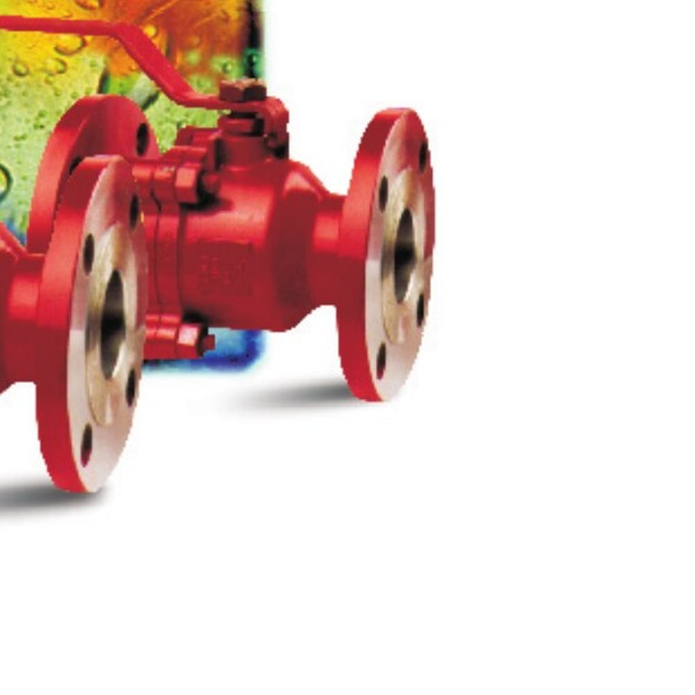
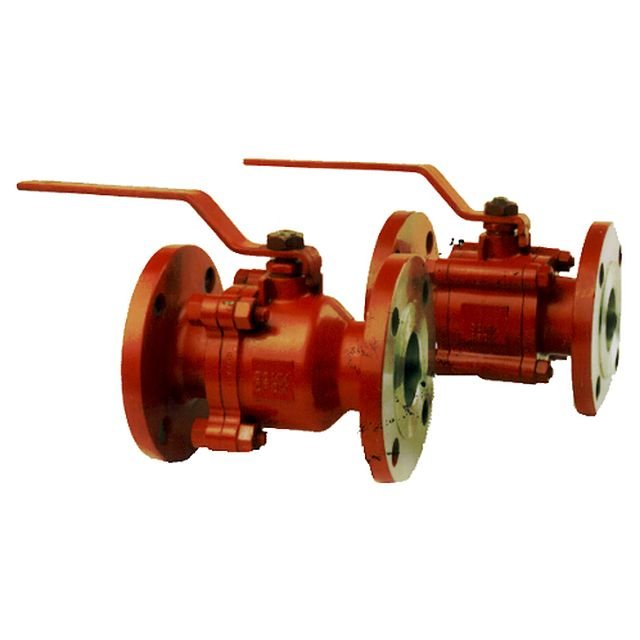
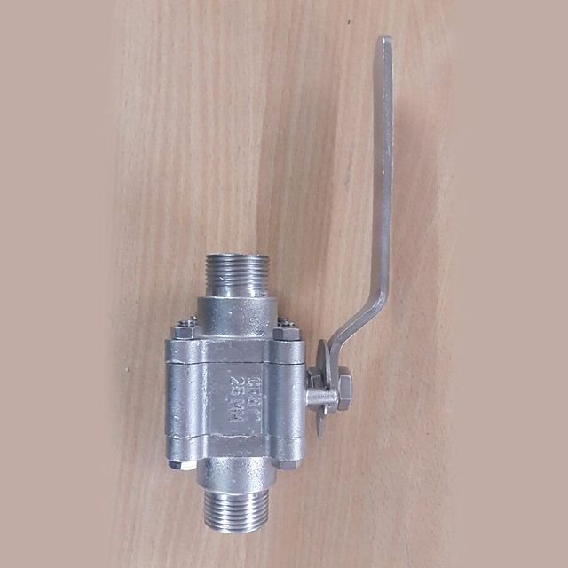
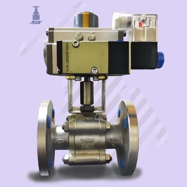
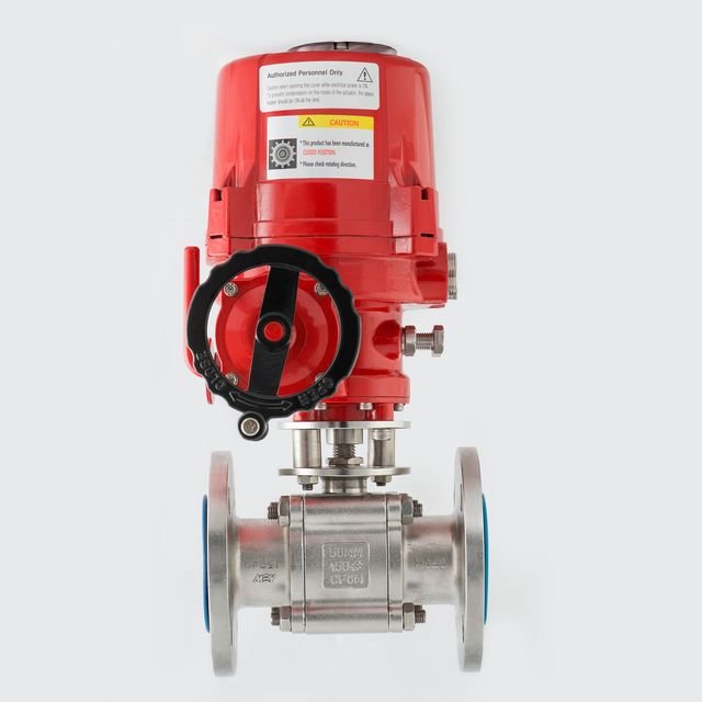
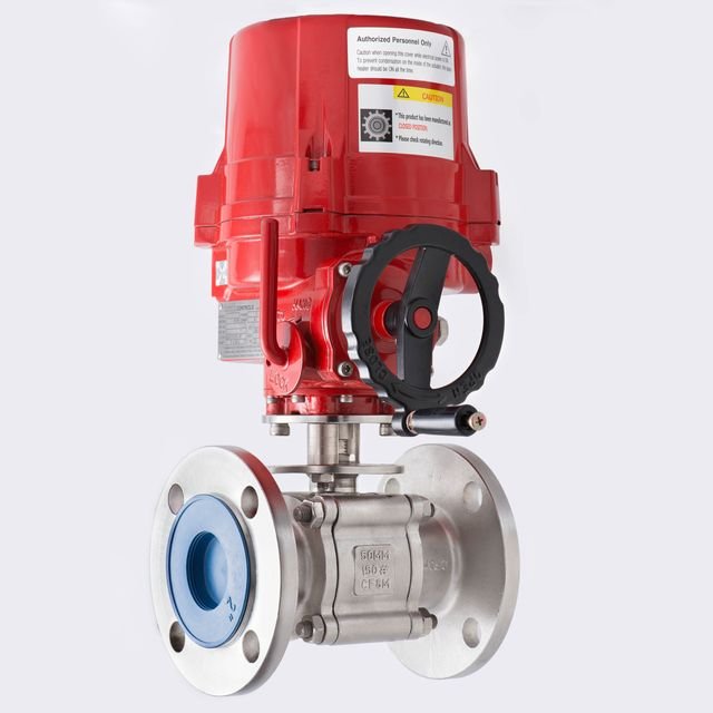
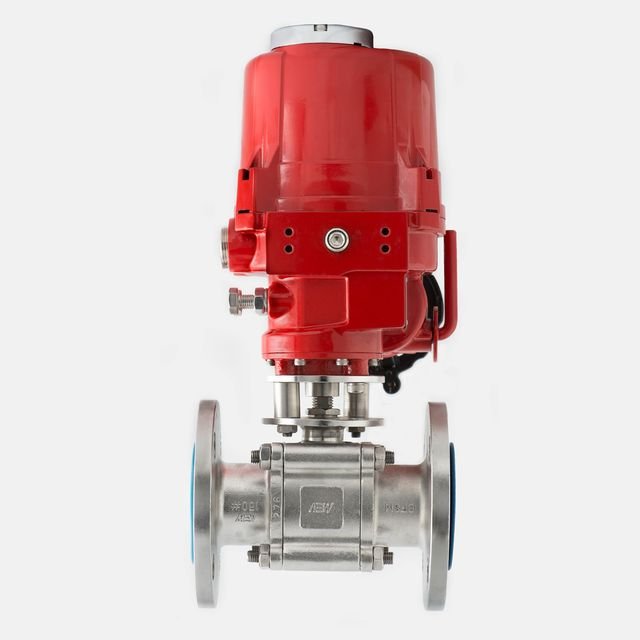
Quick quarter-turn on-off isolation with a tight, bubble-free shut-off. Cast BS 5351 ball valves in two- and three-piece construction, with a mirror-finish ball, PTFE seats and a blow-out-proof stem.
| Pressure class | Size range | |
|---|---|---|
| Class 150 | 1″ to 30″ | DN 25–750 |
| Class 300 | 1″ to 24″ | DN 25–600 |
| Class 600 | 1″ to 8″ | DN 25–200 |
| Class 800 | ½″ to 2″ | DN 15–50 |
Cast, machined and assembled to a controlled specification, from the two- or three-piece body and mirror-finish ball to the virgin-PTFE seats and blow-out-proof stem.
Cast with uniform wall thickness, smooth flowing contours and generous fillet radii to prevent stress concentrations. Designed for structural stability, mechanical strength and safe weldability. Precision machined.
All ball valves are designed with either two-piece or three-piece construction. Valves up to 2″ are investment cast.
Precision machined and buffed to a mirror-like finish for minimum wear on the seat. All balls are designed to withstand the full hydrostatic body pressure.
Soft seat rings processed from PTFE oil-free granular resins of virgin material, completely free of reclaimed processed material. Reinforced PTFE seats and seals can be provided on request.
The blow-out-proof stem is sized so that its connection to the ball can withstand the maximum operating torque satisfactorily.
All valves are lever operated, with quick quarter-turn on-off operation.
The design of the body and end-connection gasketed joint is critical. Its compression is better controlled in a fully enclosed cavity, for a stronger, leak-proof joint.
Flanges on Class 150 and Class 300 valves have a 1/16″ raised face.

One arrangement in three standard builds, carbon steel through to 316 stainless.
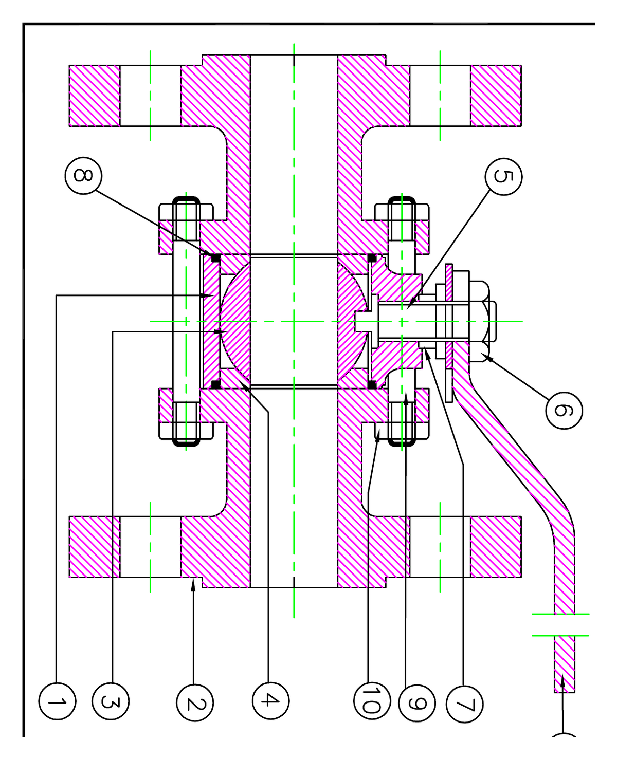
| # | Part | Carbon steelWCB | Stainless 304CF8 | Stainless 316CF8M |
|---|---|---|---|---|
| 1 | Body | WCB | CF8 | CF8M |
| 2 | End connection | WCB | CF8 | CF8M |
| 3 | Ball | CF8 | CF8 | CF8M |
| 4 | Seat | P.T.F.E. | P.T.F.E. | P.T.F.E. |
| 5 | Stem | SS410 | SS304 | SS316 |
| 6 | Stem nut | MS | SS304 | SS316 |
| 7 | Gland bush | SS410 | CF8 | CF8M |
| 8 | Packings | P.T.F.E. | P.T.F.E. | P.T.F.E. |
| 9 | Bolts | A 193-B7 | B8 | B8M |
| 10 | Nuts | A 194-2H | A 194-8 | A 194-8M |
| 11 | Lever | MS | MS | MS |
All valves up to 2″ are investment cast. Reinforced PTFE seats and seals are available on request.
| Test | Class 150 | Class 300 | Testing medium |
|---|---|---|---|
| Shell | 450 psig· 30 bar | 1125 psig· 77 bar | Kerosene / Water |
| Seat leak | 325 psig· 22 bar | 835 psig· 57 bar | Water |
Seat-leak air test provided on request. A ball valve has no backseat.
Standard face-to-face and flange data for the Class 150 cast range. Full metric data is on the GAD tab.
| Bore Ø | Face-to-face | Flange Ø | Flange thk | P.C.D. | Raised face Ø | No. holes | Hole Ø |
|---|---|---|---|---|---|---|---|
| 1″ | 5 | 4 1/4 | 7/16 | 3 1/8 | 2 | 4 | 5/8 |
| 1½″ | 6 1/2 | 5 | 9/16 | 3 7/8 | 2 7/8 | 4 | 5/8 |
| 2″ | 7 | 6 | 5/8 | 4 3/4 | 3 5/8 | 4 | 3/4 |
| 2½″ | 7 1/2 | 7 | 11/16 | 5 1/2 | 4 1/8 | 4 | 3/4 |
| 3″ | 8 | 7 1/2 | 3/4 | 6 | 5 | 4 | 3/4 |
| 4″ | 9 | 9 | 15/16 | 7 1/2 | 6 3/16 | 8 | 3/4 |
| 5″ | 10 | 10 | 15/16 | 8 1/2 | 7 5/16 | 8 | 7/8 |
| 6″ | 10 1/2 | 11 | 1 | 9 1/2 | 8 1/2 | 8 | 7/8 |
| 8″ | 11 1/2 | 13 1/2 | 1 1/8 | 11 3/4 | 10 5/8 | 8 | 7/8 |
The specifications and data in this leaflet are as accurate as possible; improvements and modifications from time to time may necessitate change in design and dimensions.
Every AEW ball valve ships to a controlled arrangement drawing. Two-piece body, mirror-finish ball, virgin-PTFE seats and a blow-out-proof stem, each part numbered, each material specified.
Materials shown for the carbon-steel (WCB) build. Full CF8 / CF8M equivalents are on the Info tab.
Complete face-to-face, flange and bolting data for the Class 150 cast range, in millimetres, taken from arrangement drawing AEW/BLV/150.
| DN · mm | NPS · in | Face-to-face | Flange Ø | Bolt circle | No. × hole Ø | Flange thk |
|---|---|---|---|---|---|---|
| 15 | ½″ | 107.9 | 90 | 60.3 | 4 × 15.87 | 9.6 |
| 20 | ¾″ | 117.3 | 100 | 69.9 | 4 × 15.87 | 11.2 |
| 25 | 1″ | 127 | 110 | 79.4 | 4 × 15.87 | 12.7 |
| 40 | 1½″ | 165.1 | 125 | 98.4 | 4 × 15.87 | 15.9 |
| 50 | 2″ | 177.8 | 150 | 120.7 | 4 × 19.05 | 17.5 |
| 65 | 2½″ | 190.5 | 180 | 139.7 | 4 × 19.05 | 20.7 |
| 80 | 3″ | 203.2 | 190 | 152.4 | 4 × 19.05 | 22.3 |
| 100 | 4″ | 228.6 | 230 | 190.5 | 8 × 19.05 | 22.3 |
| 125 | 5″ | 254 | 255 | 215.9 | 8 × 22.22 | 22.3 |
| 150 | 6″ | 266.7 | 280 | 241.3 | 8 × 22.22 | 23.9 |
| 200 | 8″ | 292.1 | 345 | 298.5 | 8 × 22.22 | 27 |
All dimensions in millimetres, as per arrangement drawing AEW/BLV/150. Face-to-face per ANSI B16.10; flange drilling per ANSI B16.5; hole Ø is the bolt-hole diameter. Class 150 covers DN15–200.
The full ball-valve catalogue and the Class 150 arrangement drawing, as print-ready PDFs for your file or tender.
Design features, materials of construction, test pressures and the full dimensional data for the BS 5351 cast ball range.


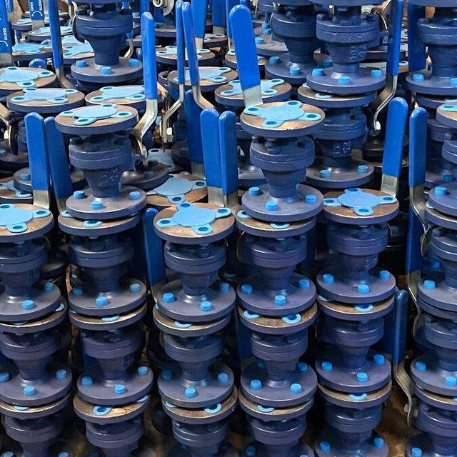
Cast, machined, and shipped.Made at the Shahibaug works in Ahmedabad, trusted on GAIL, BARC, Adani and Asian Paints lines.
Send us size, class, material, construction (two- or three-piece) and quantity, and we’ll respond with a quotation and the arrangement drawing for your file.
or call +91 98250 13325