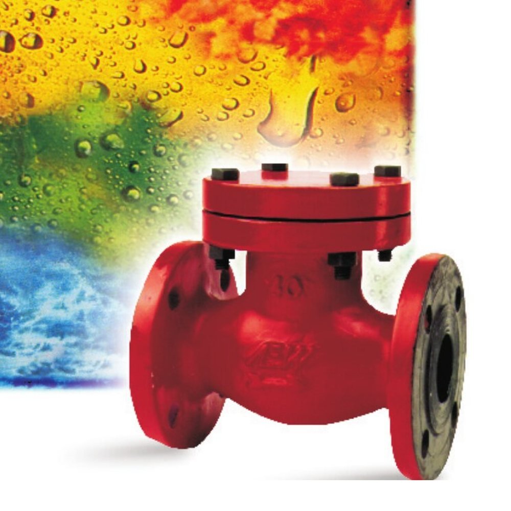
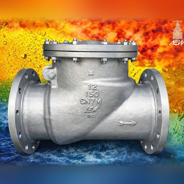
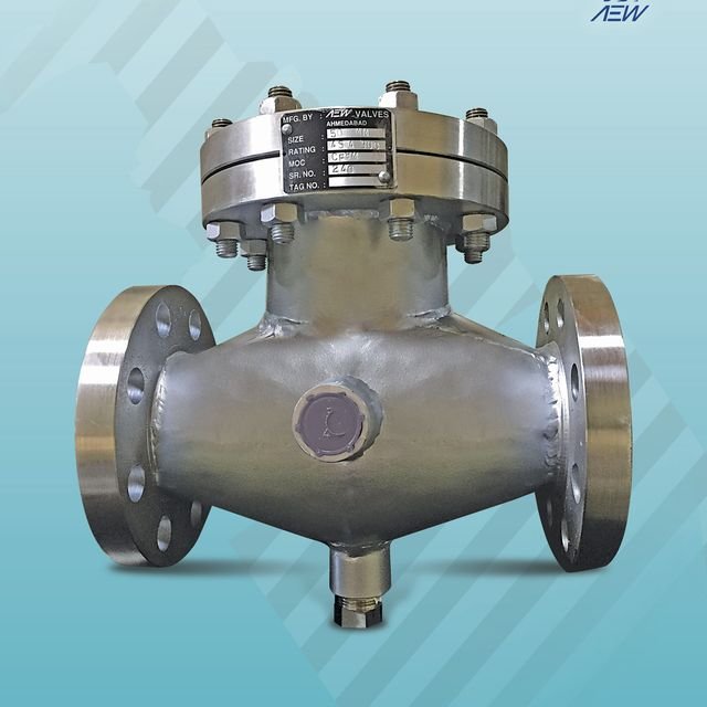
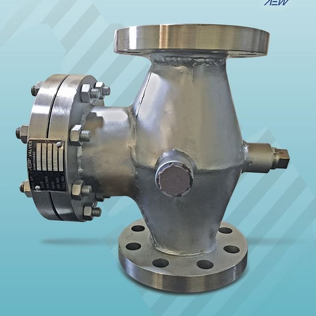
Designed to BS 1868
Cast with uniform wall thickness, smooth flowing contours and generous fillet radii to prevent stress concentrations. Designed for structural stability, mechanical strength and safe weldability. Precision machined.
Automatic non-return protection against backflow. Cast BS 1868 check valves in carbon and stainless steel, in swing and lift patterns, with hardfaced seats for long on-line service.
| Pressure class | Size range | |
|---|---|---|
| Class 150 | 1″ to 12″ | DN 25–300 |
| Class 300 | 1″ to 10″ | DN 25–250 |
| Class 600 | 1″ to 6″ | DN 25–150 |
| Class 800 | ½″ to 2″ | DN 15–50 |
Size ranges shown are for swing check valves.
Cast, machined and assembled to a controlled specification, from the bolted male/female cover and free-floating disc assembly to the hardfaced seats and fully-encased gasket.
Cast with uniform wall thickness, smooth flowing contours and generous fillet radii to prevent stress concentrations. Designed for structural stability, mechanical strength and safe weldability. Precision machined.
Male / female type, bolted cover. All working parts are accessible from the top for easy servicing.
The disc design is free-floating, enabling rotation to avoid localised wear and prolong seat life.
The disc-to-disc-carrier design lets the valve open at low differential pressure. The disc is fastened securely to the disc carrier by a lock nut and cotter pin, and the carrier is supported on a sturdy hinge pin of excellent bearing quality.
The hard-seat concept suits on-line service, where seat faces are exposed to live fluid in the open position. CA15 / Stellite facing reduces on-line seat wear for long, leak-proof service.
The gasketed joint is critical: its compression is better controlled in a fully enclosed cavity, and the possibility of the SS spiral-wound metal unwinding is eliminated, giving a strong, leak-proof body-to-cover joint.
Flanges on Class 150 and Class 300 valves have a 1/16″ raised face.

One arrangement in three standard builds, carbon steel through to 316 stainless.
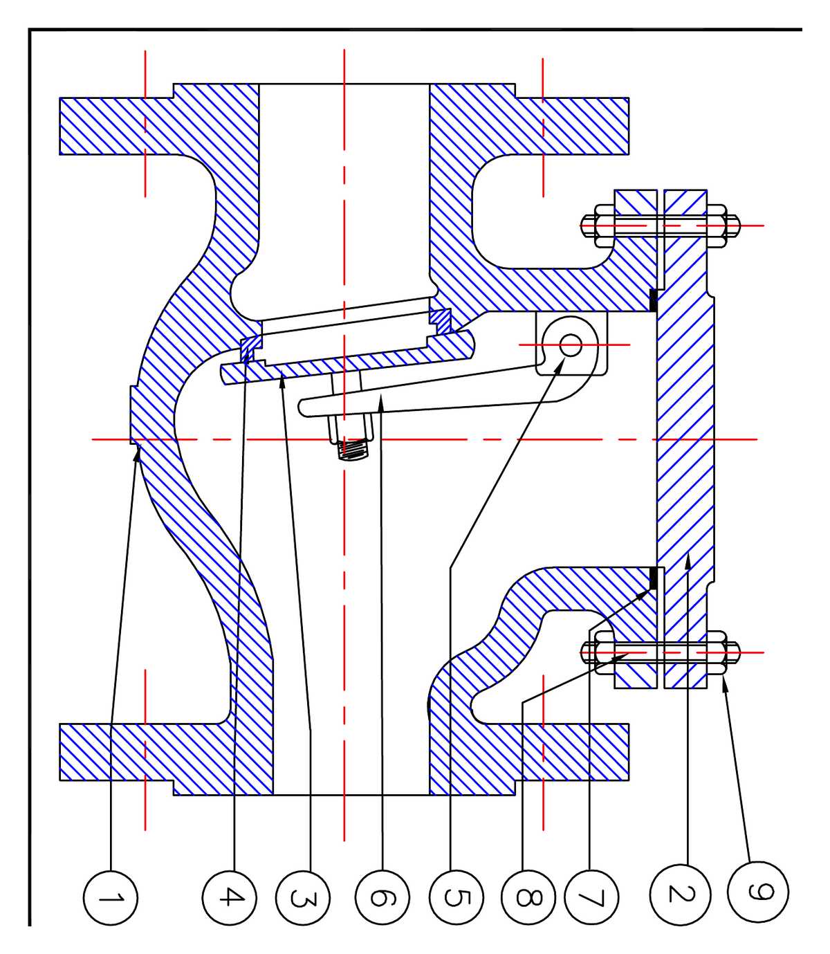
| # | Part | Carbon steelWCB | Stainless 304CF8 | Stainless 316CF8M |
|---|---|---|---|---|
| 1 | Body | WCB | CF8 | CF8M |
| 2 | Cover | WCB | CF8 | CF8M |
| 3 | Disc | CA15 / WCB+13%Cr | CF8 | CF8M |
| 4 | Seat | CA15 / Stellite-6 | CF8 | CF8M |
| 5 | Pin | SS410 | SS304 | SS316 |
| 6 | Disc holder | WCB | CF8 | CF8M |
| 7 | Packings | Graphited asbestos | P.T.F.E. | P.T.F.E. |
| 8 | Bolts | A 193-B7 | B8 | B8M |
| 9 | Nuts | A 194-2H | A 194-8 | A 194-8M |
Asbestos-free graphoil packing is available.
| Test | Class 150 | Class 300 | Testing medium |
|---|---|---|---|
| Shell | 450 psig· 30 bar | 1125 psig· 77 bar | Kerosene / Water |
| Seat leak | 325 psig· 22 bar | 835 psig· 57 bar | Water |
Seat-leak air test provided on request. A check valve has no backseat.
Standard face-to-face and flange data for the Class 150 cast range. Full metric data is on the GAD tab.
| Bore Ø | Face-to-face | Flange Ø | Flange thk | P.C.D. | Raised face Ø | No. holes | Hole Ø |
|---|---|---|---|---|---|---|---|
| 1″ | 5 | 4 1/4 | 7/16 | 3 1/8 | 2 | 4 | 5/8 |
| 1½″ | 6 1/2 | 5 | 9/16 | 3 7/8 | 2 7/8 | 4 | 5/8 |
| 2″ | 8 | 6 | 5/8 | 4 3/4 | 3 5/8 | 4 | 3/4 |
| 2½″ | 8 1/2 | 7 | 11/16 | 5 1/2 | 4 1/8 | 4 | 3/4 |
| 3″ | 9 1/2 | 7 1/2 | 3/4 | 6 | 5 | 4 | 3/4 |
| 4″ | 11 1/2 | 9 | 15/16 | 7 1/2 | 6 3/16 | 8 | 3/4 |
| 5″ | 14 | 10 | 15/16 | 8 1/2 | 7 5/16 | 8 | 7/8 |
| 6″ | 16 | 11 | 1 | 9 1/2 | 8 1/2 | 8 | 7/8 |
| 8″ | 19 1/2 | 13 1/2 | 1 1/8 | 11 3/4 | 10 5/8 | 8 | 7/8 |
The specifications and data in this leaflet are as accurate as possible; improvements and modifications from time to time may necessitate change in design and dimensions.
The swing-check arrangement: a free-floating disc on a sturdy hinge pin, bolted male/female cover, and hardfaced seats, each part numbered, each material specified. Lift-check drawings are on the Brochure tab.
Materials shown for the carbon-steel (WCB) build. Full CF8 / CF8M equivalents are on the Info tab.
Complete face-to-face, flange and bolting data for the swing-check Class 150 range, in millimetres, taken from arrangement drawing AEW/SCV/150.
| DN · mm | NPS · in | Face-to-face | Flange Ø | Bolt circle | No. × hole Ø | Flange thk |
|---|---|---|---|---|---|---|
| 50 | 2″ | 203.2 | 150 | 120.7 | 4 × 19.05 | 17.5 |
| 65 | 2½″ | 215.9 | 180 | 139.7 | 4 × 19.05 | 20.7 |
| 80 | 3″ | 241 | 190 | 152.4 | 4 × 19.05 | 22.3 |
| 100 | 4″ | 292 | 230 | 190.5 | 8 × 19.05 | 22.3 |
| 125 | 5″ | 355.6 | 255 | 215.9 | 8 × 22.22 | 22.3 |
| 150 | 6″ | 406 | 280 | 241.3 | 8 × 22.22 | 23.9 |
| 200 | 8″ | 495 | 345 | 298.5 | 8 × 22.22 | 27 |
| 250 | 10″ | 622 | 405 | 362 | 12 × 25.4 | 28.6 |
| 300 | 12″ | 698 | 485 | 431.8 | 12 × 25.4 | 30.2 |
All dimensions in millimetres, as per arrangement drawing AEW/SCV/150. Face-to-face per ASME B16.10; flange drilling per ASME B16.5; hole Ø is the bolt-hole diameter. The swing-check range covers DN50–300; the lift-check range (AEW/LCV/150) covers DN25–200.
The full check-valve catalogue and the arrangement drawings for both the swing and lift patterns, as print-ready PDFs for your file or tender.


Cast, machined, and shipped.Made at the Shahibaug works in Ahmedabad, trusted on GAIL, BARC, Adani and Asian Paints lines.
Send us size, class, material, pattern (swing or lift) and quantity, and we’ll respond with a quotation and the arrangement drawing for your file.
or call +91 98250 13325